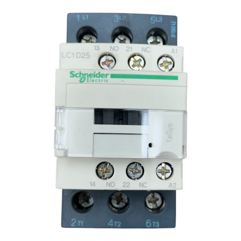
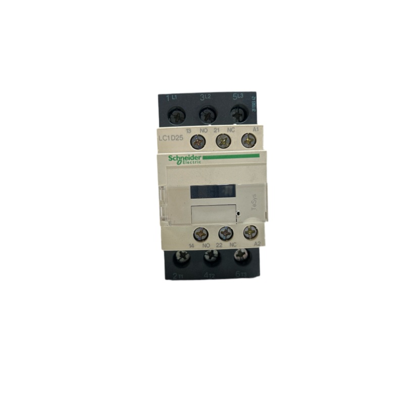
Schneider Electric, LC1D25B7, TeSys Contactor
Range of ProductTeSys DecaProduct or Component TypeContactorDevice short nameLC1DContactor applicationResistive loadMotor controlUtilisation categoryAC-1AC-3AC-4AC-3ePoles description3P[Ue] rated operational voltagePower circuit
Category: Contactors
-
Range of Product TeSys Deca Product or Component Type Contactor Device short name LC1D Contactor application Resistive load
Motor controlUtilisation category AC-1
AC-3
AC-4
AC-3ePoles description 3P [Ue] rated operational voltage Power circuit <= 690 V AC 25...400 Hz
Power circuit <= 300 V DC[Ie] rated operational current 25 A (at <140 F (60 C)) at <= 440 V AC AC-3 for power circuit
40 A (at <140 F (60 C)) at <= 440 V AC AC-1 for power circuit
25 A (at <140 F (60 C)) at <= 440 V AC AC-3e for power circuit[Uc] control circuit voltage 24 V AC 50/60 Hz Complementary
Motor power kW 5.5 kW at 220…230 V AC 50/60 Hz (AC-3)
11 kW at 380…400 V AC 50/60 Hz (AC-3)
11 kW at 415…440 V AC 50/60 Hz (AC-3)
15 kW at 500 V AC 50/60 Hz (AC-3)
15 kW at 660…690 V AC 50/60 Hz (AC-3)
5.5 kW at 400 V AC 50/60 Hz (AC-4)
5.5 kW at 220…230 V AC 50/60 Hz (AC-3e)
11 kW at 380…400 V AC 50/60 Hz (AC-3e)
11 kW at 415…440 V AC 50/60 Hz (AC-3e)
15 kW at 500 V AC 50/60 Hz (AC-3e)
15 kW at 660…690 V AC 50/60 Hz (AC-3e)Maximum Horse Power Rating 3 hp at 230/240 V AC 50/60 Hz for 1 phase motors
2 hp at 115 V AC 50/60 Hz for 1 phase motors
7.5 hp at 230/240 V AC 50/60 Hz for 3 phase motors
15 hp at 460/480 V AC 50/60 Hz for 3 phase motors
20 hp at 575/600 V AC 50/60 Hz for 3 phase motors
7.5 hp at 200/208 V AC 50/60 Hz for 3 phase motorsCompatibility code LC1D Pole contact composition 3 NO Protective cover With [Ith] conventional free air thermal current 10 A (at 140 F (60 C)) for signalling circuit
40 A (at 140 F (60 C)) for power circuitIrms rated making capacity 140 A AC for signalling circuit conforming to IEC 60947-5-1
250 A DC for signalling circuit conforming to IEC 60947-5-1
450 A at 440 V for power circuit conforming to IEC 60947Rated breaking capacity 450 A at 440 V for power circuit conforming to IEC 60947 [Icw] rated short-time withstand current 240 A 104 F (40 C) – 10 s for power circuit
380 A 104 F (40 C) – 1 s for power circuit
50 A 104 F (40 C) – 10 min for power circuit
120 A 104 F (40 C) – 1 min for power circuit
100 A – 1 s for signalling circuit
120 A – 500 ms for signalling circuit
140 A – 100 ms for signalling circuitAssociated fuse rating 10 A gG for signalling circuit conforming to IEC 60947-5-1
63 A gG at <= 690 V coordination type 1 for power circuit
40 A gG at <= 690 V coordination type 2 for power circuitAverage impedance 2 mOhm – Ith 40 A 50 Hz for power circuit Power dissipation per pole 3.2 W AC-1
1.25 W AC-3
1.25 W AC-3e[Ui] rated insulation voltage Power circuit 690 V IEC 60947-4-1
Power circuit 600 V CSA
Power circuit 600 V UL
Signalling circuit 690 V IEC 60947-1
Signalling circuit 600 V CSA
Signalling circuit 600 V ULOvervoltage category III pollution degree 3 [Uimp] rated impulse withstand voltage 6 kV IEC 60947 Safety reliability level B10d = 1369863 cycles contactor with nominal load EN/ISO 13849-1
B10d = 20000000 cycles contactor with mechanical load EN/ISO 13849-1Mechanical durability 15 Mcycles Electrical durability 1.65 Mcycles 25 A AC-3 <= 440 V
1.4 Mcycles 40 A AC-1 <= 440 V
1.65 Mcycles 25 A AC-3e <= 440 VControl circuit type AC 50/60 Hz standard Coil technology Without built-in suppressor module Control circuit voltage limits 0.3…0.6 Uc (-40158 F (-4070 C)):drop-out AC 50/60 Hz
0.8…1.1 Uc (-40140 F (-4060 C)):operational AC 50 Hz
0.85…1.1 Uc (-40140 F (-4060 C)):operational AC 60 Hz
1…1.1 Uc (140158 F (6070 C)):operational AC 50/60 HzInrush power in VA 70 VA 60 Hz cos phi 0.75 (at 68 F (20 C))
70 VA 50 Hz cos phi 0.75 (at 68 F (20 C))Hold-in power consumption in VA 7.5 VA 60 Hz cos phi 0.3 (at 68 F (20 C))
7 VA 50 Hz cos phi 0.3 (at 68 F (20 C))Heat dissipation 23 W at 50/60 Hz Operating time 12…22 ms closing
4…19 ms openingMaximum operating rate 3600 cyc/h at 60 C Connections – terminals Control circuit: screw clamp terminals 1 0.0020.006 in (14 mm) – cable stiffness: flexible without cable end
Control circuit: screw clamp terminals 2 0.0020.006 in (14 mm) – cable stiffness: flexible without cable end
Control circuit: screw clamp terminals 1 0.0020.006 in (14 mm) – cable stiffness: flexible with cable end
Control circuit: screw clamp terminals 2 0.0020.004 in (12.5 mm) – cable stiffness: flexible with cable end
Control circuit: screw clamp terminals 1 0.0020.006 in (14 mm) – cable stiffness: solid without cable end
Control circuit: screw clamp terminals 2 0.0020.006 in (14 mm) – cable stiffness: solid without cable end
Power circuit: screw clamp terminals 1 0.0040.02 in (2.510 mm) – cable stiffness: flexible without cable end
Power circuit: screw clamp terminals 2 0.0040.02 in (2.510 mm) – cable stiffness: flexible without cable end
Power circuit: screw clamp terminals 1 0.0020.02 in (110 mm) – cable stiffness: flexible with cable end
Power circuit: screw clamp terminals 2 0.0020.009 in (1.56 mm) – cable stiffness: flexible with cable end
Power circuit: screw clamp terminals 1 0.0020.02 in (1.510 mm) – cable stiffness: solid without cable end
Power circuit: screw clamp terminals 2 0.0040.02 in (2.510 mm) – cable stiffness: solid without cable endTightening torque Control circuit 15.05 lbf.in (1.7 N.m) screw clamp terminals flat 6 mm
Control circuit 15.05 lbf.in (1.7 N.m) screw clamp terminals Philips No 2
Power circuit 22.1 lbf.in (2.5 N.m) screw clamp terminals flat 6 mm
Power circuit 22.1 lbf.in (2.5 N.m) screw clamp terminals Philips No 2
Control circuit 15.05 lbf.in (1.7 N.m) screw clamp terminals pozidriv No 2
Power circuit 22.1 lbf.in (2.5 N.m) screw clamp terminals pozidriv No 2Auxiliary contact composition 1 NO + 1 NC Auxiliary contacts type Mechanically linked 1 NO + 1 NC IEC 60947-5-1
Mirror contact 1 NC IEC 60947-4-1Signalling circuit frequency 25…400 Hz Minimum switching voltage 17 V for signalling circuit Minimum switching current 5 mA for signalling circuit Insulation resistance > 10 MOhm for signalling circuit Non-overlap time 1.5 ms on de-energisation between NC and NO contact
1.5 ms on energisation between NC and NO contactMounting Support Plate
RailEnvironment
Standards CSA C22.2 No 14
EN 60947-4-1
EN 60947-5-1
IEC 60947-4-1
IEC 60947-5-1
UL 60947-4-1
IEC 60335-1:Clause 30.2
IEC 60335-2-40:Annex JJ
UL 60335-2-40:Annex JJ
CSA C22.2 No 60947-4-1Product Certifications UL
CCC
CSA
Marine
UKCA
EAC
CB SchemeIP degree of protection IP20 front face IEC 60529 Protective treatment THIEC 60068-2-30 Climatic withstand IACS E10 exposure to damp heat
IEC 60947-1 Annex Q category D exposure to damp heatPermissible ambient air temperature around the device -40140 F (-4060 C)
140158 F (6070 C) with deratingOperating altitude 0…9842.52 ft (0…3000 m) Fire resistance 1562 F (850 C) IEC 60695-2-1 Flame retardance V1 conforming to UL 94 Mechanical robustness Vibrations contactor open 2 Gn, 5…300 Hz)
Vibrations contactor closed 4 Gn, 5…300 Hz)
Shocks contactor closed 15 Gn for 11 ms)
Shocks contactor open 8 Gn for 11 ms)Height 3.3 in (85 mm) Width 1.8 in (45 mm) Depth 3.6 in (92 mm) Net Weight 0.82 lb(US) (0.37 kg) Ordering and shipping details
Category US10I1222354 Discount Schedule 0I12 GTIN 3389110349658 Returnability Yes Country of origin ID Packing Units
Unit Type of Package 1 PCE Number of Units in Package 1 1 Package 1 Height 1.97 in (5.000 cm) Package 1 Width 3.54 in (9.000 cm) Package 1 Length 4.33 in (11.000 cm) Package 1 Weight 14.850 oz (421.000 g) Unit Type of Package 2 S02 Number of Units in Package 2 20 Package 2 Height 5.91 in (15.000 cm) Package 2 Width 11.81 in (30.000 cm) Package 2 Length 15.75 in (40.000 cm) Package 2 Weight 18.969 lb(US) (8.604 kg) Unit Type of Package 3 P06 Number of Units in Package 3 320 Package 3 Height 29.53 in (75.000 cm) Package 3 Width 23.62 in (60.000 cm) Package 3 Length 31.50 in (80.000 cm) Package 3 Weight 323.498 lb(US) (146.736 kg)
Reviews
There are no reviews yet.